The Ultimate Guide to Low-Voltage Circuit Protection: Comparing MCB, RCCB, and RCBO
- Introduction
In low-voltage electrical distribution networks, protective switch gear is vital to ensure operational safety, minimize fire hazards, and prevent damage to downstream equipment.
The primary anomalies encountered in these networks are overcurrents (subdivided into overloads and short circuits) and earth leakage currents.
This report provides a comparative engineering analysis of the primary miniature protective devices utilized today:
- Miniature Circuit Breakers (MCBs),
- Earth Leakage Circuit Breakers (ELCBs),
- Residual Current Circuit Breakers (RCCBs),
- Residual Current Breakers with Overcurrent Protection (RCBOs).
- Device Analysis & Working Principles
2.1 Miniature Circuit Breaker (MCB)
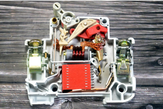
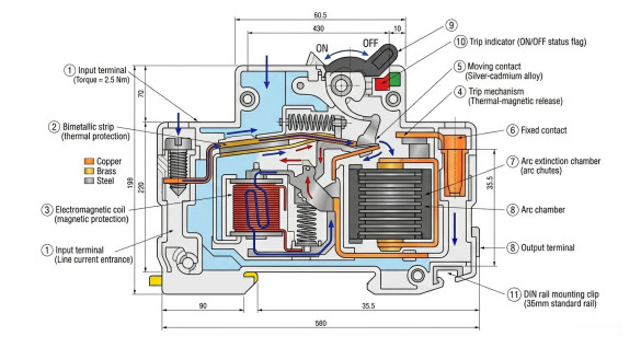
An MCB is a mechanical switching device capable of making, carrying, and breaking currents under normal circuit conditions, as well as breaking currents under specified abnormal conditions like short circuits.
a) Protection Mechanisms:
Thermal Protection (Overload): Utilizes a calibrated bimetallic strip. Continuous overcurrent heats the strip, causing it to bend due to differing thermal expansion coefficients. This mechanical deflection releases the trip latch.
b) Magnetic Protection (Short Circuit): Utilizes an internal solenoid or coil. High-magnitude fault currents induce an instantaneous magnetic field that pulls the plunger, striking the trip bar to break the contacts immediately.
c) MCB Tripping Curves and Selection
While all MCBs protect against overloads and short circuits, they are manufactured with different magnetic trip thresholds to match specific types of electrical loads. These characteristics are defined by standard Tripping Curves (Type B, C, and D) under international standard IEC 60898-1.
Selecting the correct curve prevents nuisance tripping (when a circuit breaker trips due to normal, brief spikes in current, like a motor starting up).
| MCB Type | Magnetic Trip Range | Typical Application |
| Type B | 3 × Iₙ ~ 5 × Iₙ | Residential lighting, socket circuits, resistive loads |
| Type C | 5 × Iₙ ~ 10 × Iₙ | Commercial lighting, fans, small motors, air conditioners |
| Type D | 10 × Iₙ ~ 20 × Iₙ | Large motors, transformers, welding machines |
Multiplier of Rated Current (In)
i) Type B Tripping Curve
- Magnetic Trip Threshold: 3 x Iₙ ~ 5 x Iₙ (where Iₙ is the rated nominal current).
- Characteristics: This curve trips quickly at relatively low overcurrents. It is designed for purely resistive loads or circuits where switching surges are practically non-existent.
- Primary Applications: Domestic lighting circuits, standard residential wall outlets, and electronics without inductive coils.
ii) Type C Tripping Curve
- Magnetic Trip Threshold: 5 x Iₙ ~ 10 x Iₙ
- Characteristics: This is the most common commercial profile. It provides a moderate delay that allows the breaker to ride through mild, everyday current spikes without tripping.
- Primary Applications: Commercial fluorescent lighting banks, small air conditioners, fans, computer servers, and small workshop power tools where inductive loads cause minor inrush currents.
iii) Type D Tripping Curve
- Magnetic Trip Threshold: 10 x Iₙ ~ 20 x Iₙ
- Characteristics: Highly delayed magnetic response. Designed specifically to tolerate massive, transient current spikes that occur when heavy inductive machinery magnetization occurs.
- Primary Applications: Large industrial motors, welding machines, X-ray equipment, and high-power industrial transformers.
- Practical Selection Guide
| Application | Recommended Device |
| Normal lighting circuit | MCB Type B or Type C |
| Socket outlet circuit | RCBO or MCB + RCCB |
| Water heater / wet area | RCBO or RCCB 30mA |
| Motor load | MCB Type C or Type D, depending on inrush current |
| Main single-phase incoming protection | 2P RCCB with suitable MCB/MCCB |
| Three-phase main distribution | 4P RCCB/isolator with suitable overcurrent protection |
2.2 Earth Leakage Circuit Breaker (ELCB) & Residual Current Breaker (RCB/RCCB)
While historically grouped together, modern engineering practice distinguishes between voltage-operated and current-operated leakage devices:
a) Voltage-Operated ELCB :Relies on a fault voltage detection coil connected between the equipment metallic enclosure and an auxiliary earth electrode. If the enclosure voltage rises to a dangerous level (typically greater than 50V), the coil trips the breaker.
Note: These are largely obsolete because if the earth wire path is broken, the device cannot trip.
b) Current-Operated ELCB / RCCB / RCB:Operates on the principle of current balance via a Current Transformer (CT) or Zero-Sequence Current Transformer (ZSCT).
Σ I = I live – I Neutral = 0
Where :
- I live: The current flowing into the circuit through the live (phase) wire.
- I Neutral: The current returning out of the circuit through the neutral wire.
- Σ I = 0 : In a perfectly normal, safe operating condition, the current going in must exactly equal the current coming out.
- The net sum (Σ) of these opposing currents inside the sensing coil is zero.·
Under healthy conditions, the vector sum of currents passing through the phase and neutral conductors equals zero.
If current leaks to earth (e.g., via human contact or degraded insulation), an imbalance occurs:
Σ I = I Leakage ≠ 0
This net differential current induces a residual flux in the transformer core, generating a secondary voltage that energizes a sensitive relay to trip the mechanism.
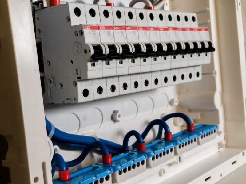
Source: Vladyslav Zamrii / Getty Images
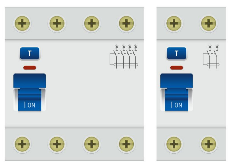
2.3 Residual Current Breaker with Overcurrent Protection (RCBO)
An RCBO integrates the dual-functionality of an MCB and an RCCB into a single compact housing. It monitors and protects against overloads, short circuits, and residual earth leakage currents simultaneously, preventing an earth fault on one branch circuit from shutting down an entire distribution board.
3. Engineering Parameter Comparison Matrix
The following table summarizes the operational properties of low-voltage protective devices:
| Device Type | Primary Protection Focus | Tripping Mechanism | Typical Ratings | IEC / International Standard |
| MCB | Overload & Short Circuit | Bimetallic Strip + Solenoid | 0.5A – 125A (Interrupting: 4.5kA – 25kA) | IEC 60898-1 / IEC 60947-2 |
| ELCB (Voltage) | Enclosure Fault Voltage | Voltage Sensing Coil | Obsolete in modern installations | Historical reference |
| RCB / RCCB | Earth Leakage & Shock Prevention | Core Balance Current Transformer | Sensitivities: 10mA, 30mA, 100mA, 300mA | IEC 61008-1 |
| RCBO | Overload, Short Circuit & Earth Leakage | Combined Thermal Magnetic + Current Transformer | Combined MCB/RCCB curves | IEC 61009-1 |
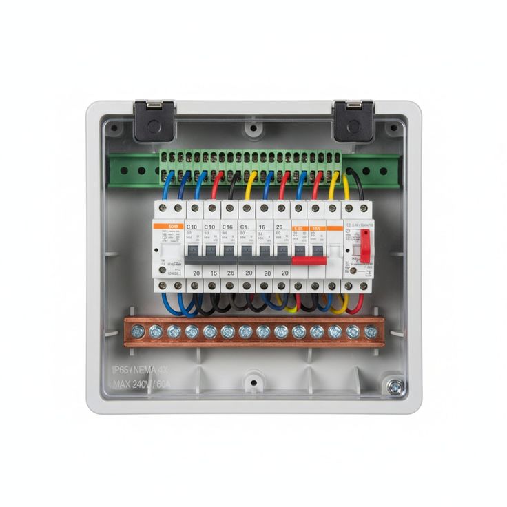
- Pole Configurations
The selection of pole types (Single-Pole to Four-Pole) dictates how many conductors are simultaneously disconnected during a fault or maintenance event. Choosing the wrong configuration can leave neutral lines energized, leading to severe shock hazards even when a breaker appears “tripped.”
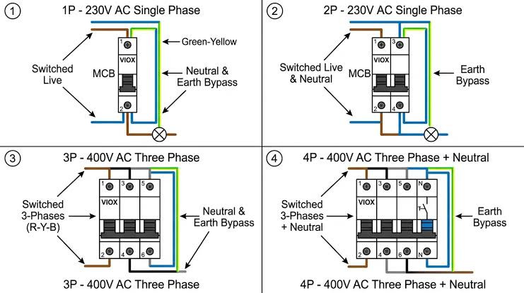
Source: VIOX Electric
1-Pole (1P): Disconnects only the phase (live) wire. It is used exclusively for single-phase branch circuits (e.g., standard lighting or small domestic outlets) where the neutral is tied permanently to a shared return bar.
- 2-Pole (2P):Disconnects both the phase and neutral wires simultaneously. This is essential for main incoming switches in single-phase consumer units, ensuring complete isolation of the entire downstream installation from back-feeding neutral voltages.
- 3-Pole (3P):Disconnects all three active phases (L1, L2, L3) simultaneously without breaking the neutral. Primarily used for balanced three-phase loads, such as industrial induction motors or delta-connected equipment where a neutral line is absent.
- 4-Pole (4P):Disconnects all three phases as well as the neutral line. This configuration is mandatory at the main intake of three-phase, four-wire distribution networks (TT or TN-S earthing configurations) to guarantee full electrical isolation during maintenance or unbalanced zero-sequence fault events.
- Conclusion
Low-voltage circuit protection requires balancing structural infrastructure safety with personal safety. Overcurrent devices (MCBs) protect wiring assets from thermal degradation caused by overloads and magnetic forces during short circuits, but their high tripping thresholds leave humans completely unprotected against small leakage currents.
Conversely, residual current devices (RCCBs) mitigate lethal path-to-ground shocks and fire hazards by tracking current imbalances using a Zero-Sequence Current Transformer, but they cannot protect themselves against high-current overloads.
Ultimately, modern electrical codes prefer integrated topologies like the RCBO or the strategic cascading of MCBs downstream of an RCCB. This approach guarantees full electrical protection while preserving selectivity, keeping localized faults from causing complete facility blackouts.
References
- International Standards (IEEE / IEC)
- International Electrotechnical Commission. (2015). Electrical installations of buildings – Part 4-41: Protection for safety – Protection against electric shock (IEC Standard No. 60364-4-41). Geneva, Switzerland: IEC.
- International Electrotechnical Commission. (2019). Electrical accessories – Circuit-breakers for overcurrent protection for household and similar installations – Part 1: Circuit-breakers for a.c. operation (IEC Standard No. 60898-1). Geneva, Switzerland: IEC.
- International Electrotechnical Commission. (2020). Residual current operated circuit-breakers without integral overcurrent protection for household and similar uses (RCCBs) – Part 1: General rules (IEC Standard No. 61008-1). Geneva, Switzerland: IEC.